×
- Quick Links
- Overview
- What's new
- Innovations
- Buy

All your PDF Underlays can be managed easily in it. You can check their information, find where they are located, directly open one in PDF reader, detach them to make the drawing lighter, etc.

Various properties and data of an object can be extracted and inserted to the current drawing as a table, or exported to a .csv / .xls file. All data you need are in one table at a time.

Developed based on Visual Studio Code from Microsoft™, Lisp Debugger helps check and debug your codes one by one or step by step, making your lisp programs more correct.

The overlapped objects can be checked and selected with ease by SELECTIONCYCLING. They will be listed in a dialog box called Selection Set for you to choose the one you really want.
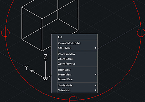
More options have been added to the right-click menu of 3DORBIT, such as Virtual Aids, Shade Mode, Zoom Windows/Extents/Previous, Reset/Preset/Named View, etc., making 3DORBIT easier and handier to use.
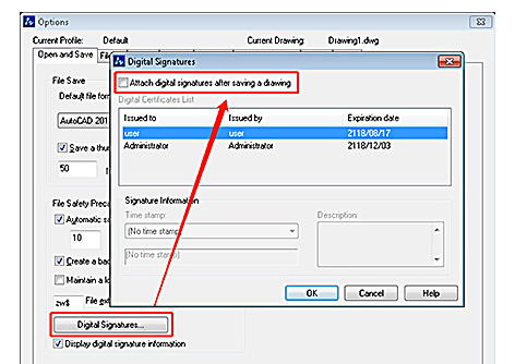
Digital Signature can now be attached to the current drawing or a batch of drawings in DWG2004, DWG2010, DWG2013 and DWG2018, and can also be verified by SIGVALIDATE.
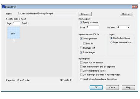
PDF, together with the geometric objects, hatch objects, raster images and TrueType text contained in it, can now be imported to the current drawing, making it convenient to get and edit what you want from PDF files.
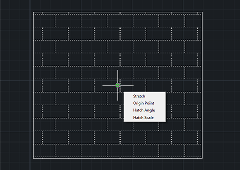
Multifunctional Grip Menu for PLINE and HATCH is now supported, offering multiple options like Stretch, Add or Remove Vertex, Convert to Arc, etc. You can now edit polylines and hatched objects more conveniently and efficiently.
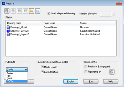
Drawings can now be plotted, published and exported to DWFx format.
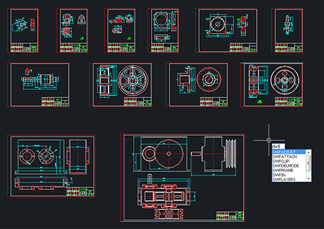
More functions of DWF/DWFx Underlay, such as snapping objects, managing layers, clipping, adjusting display effect, etc. are supported, which means that you can handily edit off-the-shelf designs, rather than starting from zero.
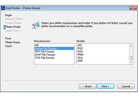
ZWCAD 2019 SP1 now supports plotting EMF files.
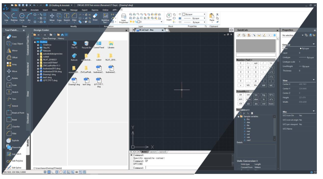
In the former version, Dark is the default color scheme helping reduce visual fatigue. Now Light is also available as another option to satisfy different preferences.
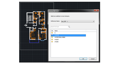
Both PDF and DWFx files can be attached to your current drawing as underlays and references, so that you can continue to work on the existing designs, instead of starting from scratch.
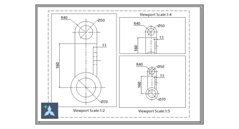
Annotations like dimensions and texts can be set as Annotative Objects, enabling their sizes to be adjusted automatically according to different view scales in Model space or Layout viewport, to guarantee their readability on screen and in plotting.
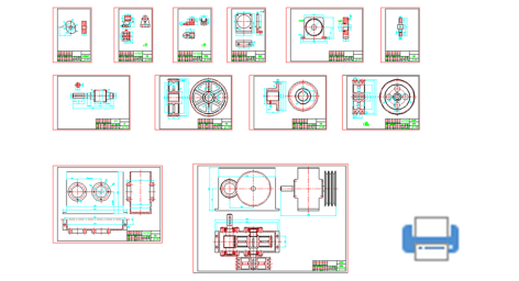
With Smart Plot, multiple frames can be plotted all at once from the Model space with ZWPLOT command. More efficient plotting process is realized.
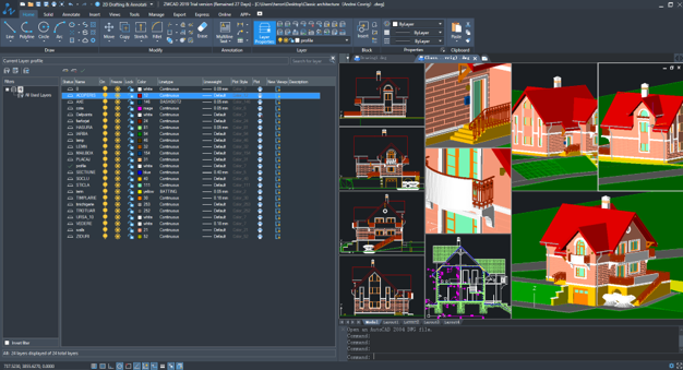
Layer Manager is now turned into a palette, which means that you can operate in the drawing area with the Layer Manager on and the adjustments in it can be updated instantly in the drawing area.
Polar tracking on Z-Axis is available now in 3D design. You can draw lines parallel to Z-Axis easily without any other construction lines or switching to different views.
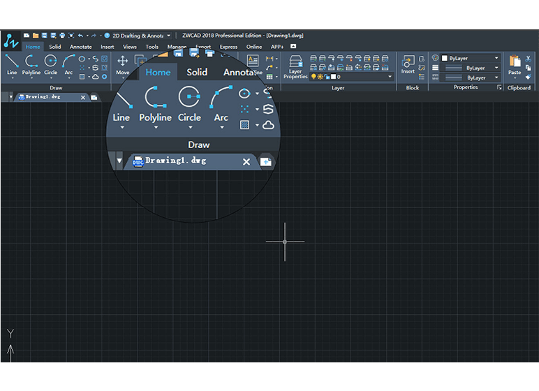
The default canvas background has been made darker while the Ribbon and menu become lighter, making the whole interface more visual-friendly, and helping you distinguish different areas more easily.
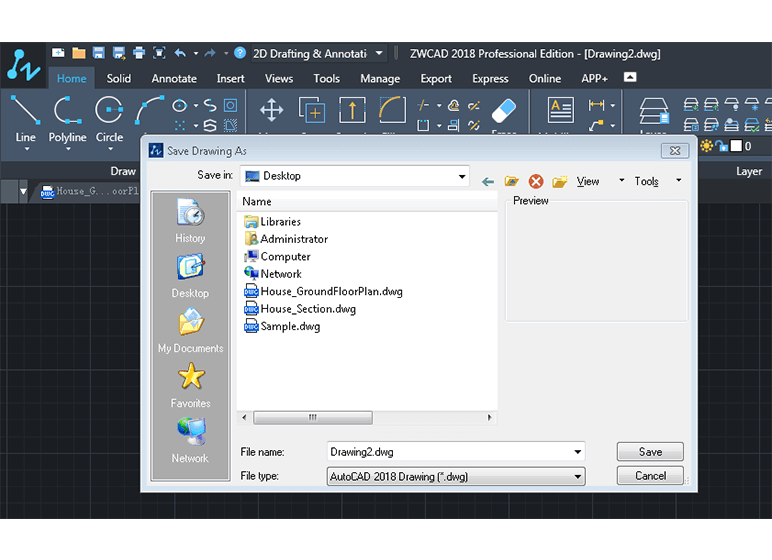
You can create, open and save any drawing in this format, realizing seamless compatibility with different versions of .dwg files. Sharing and co-working become much easier.
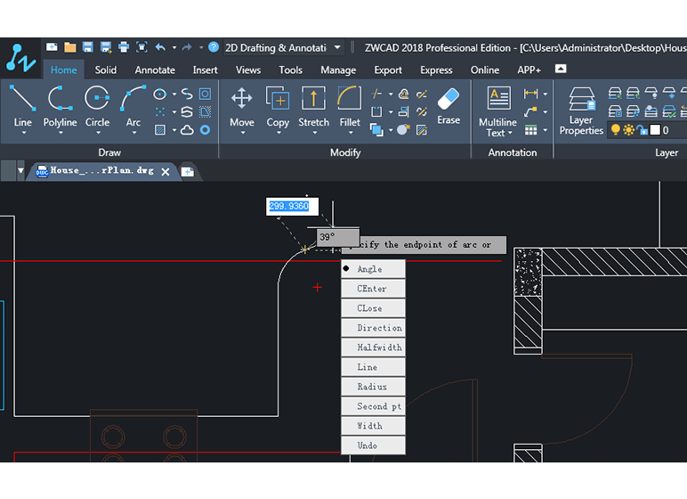
It provides command tooltips which display dynamically updated information near the cursor. You can specify options and values in the tooltip box when a command is in progress.
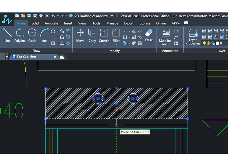
Instead of relying on the original boundary grips to adjust the shape of a hatched object, now you can change its shape anytime since the boundary grips become its built-in part.
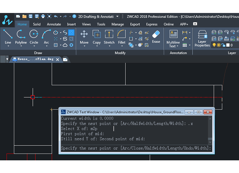
It helps specify a new coordinate location by combining the X, Y, Z values of different locations, simplifying your drawing since no extra supporting lines or graphics are needed.
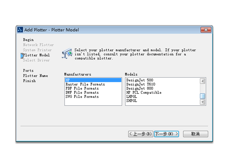
The SHPGL/LHPGL Plotters, ZWCAD Virtual Eps Plotter and SVG Plotter are now all available to plot PLT files, EPS files and SVG files.
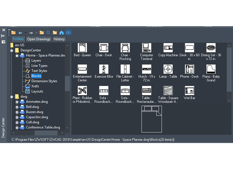
Manages and accesses to drawing contents such as blocks, xrefs, layers and others on your computer or on a network drive.
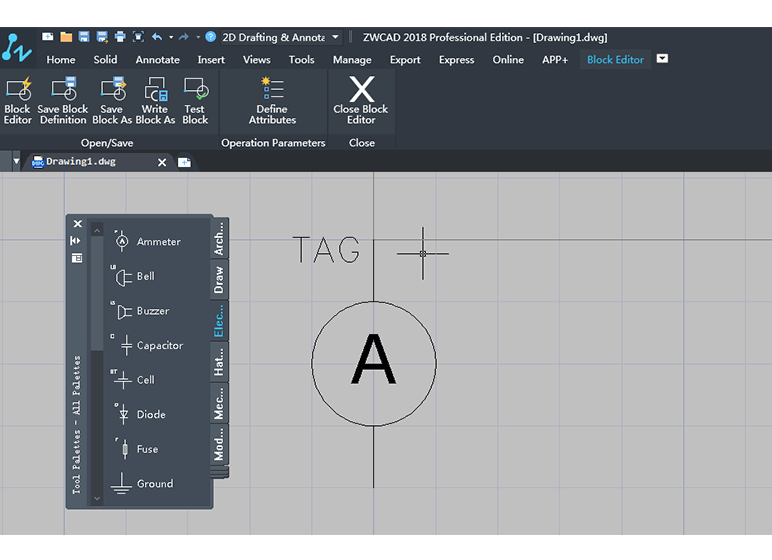
Opens an independent area for creating and editing block definitions. You can save as a block, define attributes and edit non uniformly scale block in Block Editor.
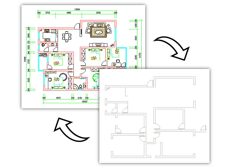
Restores the last change or set of changes made to layer settings. Using layer properties manager to change the layers, you can easily input LAYERP to restore the layer settings back.
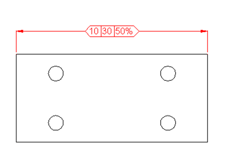
Adds or removes inspection information for a selected dimension, so you will know how frequently the manufactured parts should be checked to make sure the dimension and tolerances are precise enough.
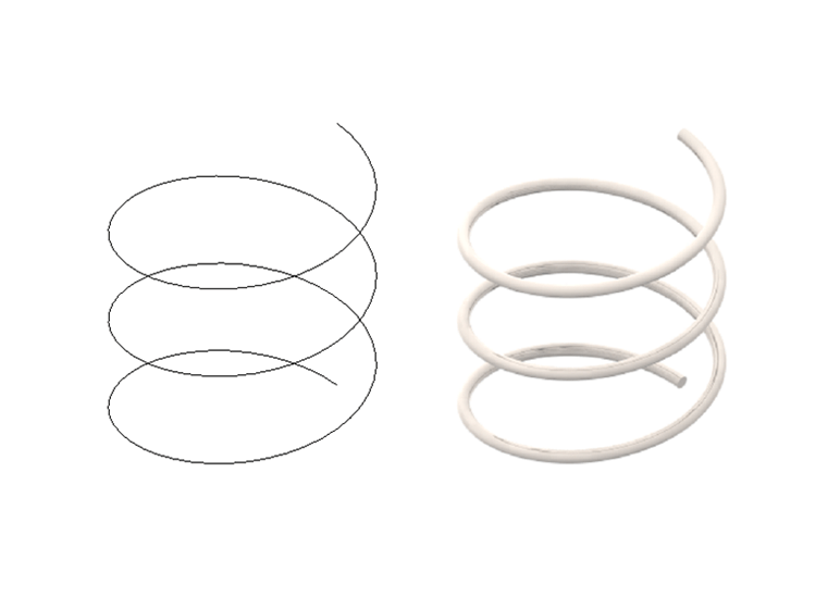
Creates a 2D spiral or 3D spring. Along with a spiral path you can create a 3D spring model.
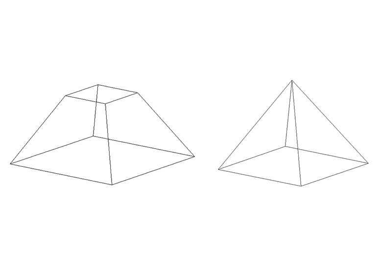
Creates a 3D solid pyramid. You can easily create a pyramid model by specifying the center base point, the middle edge point, and another point to set the height.
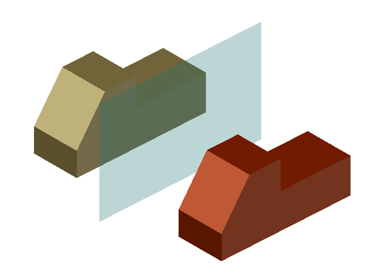
Creates a mirrored copy of selected 3D objects across a mirroring plane. You can determine the mirroring plane by multiple ways such as Object, 3 Points, XY/YX/ZX and others.
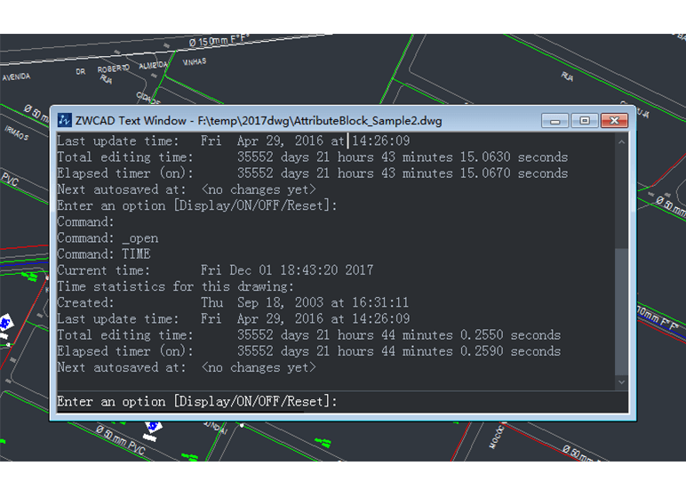
Displays the date and time statistics of a drawing, including the Current Time, Created Time for the drawing, Total Editing Time for the drawing, etc.
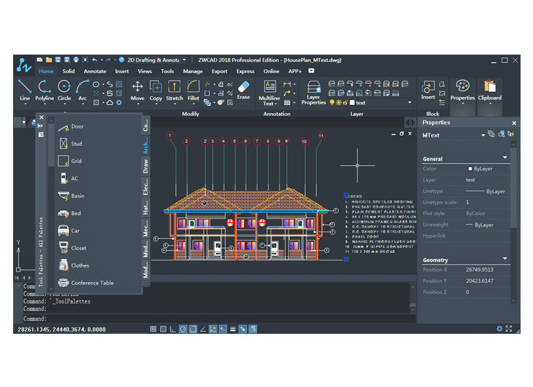
The new UI has lower brightness, higher contrast, your eyes will feel more comfortable even if you stare on the interface for a long time. At the same time, it is neater and flatter, which is the trending style of software interface. The skin color is close to the background color of the model space, which makes it more professional.
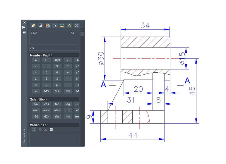
Perform calculation within CAD just as you would with a desktop calculator.
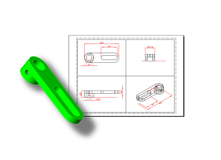
Project 3D solids onto a 2D plane parallel, create 2D profile images.
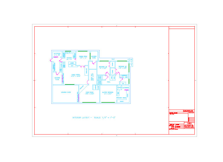
Use Mvsetup to set up a drawing for plotting directly from model space. Or on a named layout, you can insert a title block into the drawing, and create a set of layout viewports in the title block area. You can specify a global scale as the ratio between the scale of the title block in the layout and what you have created in model space.
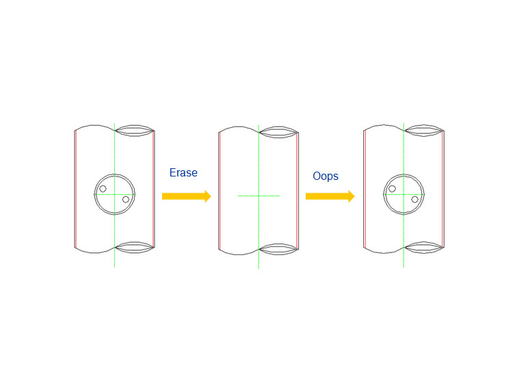
Restores objects erased by the latest ERASE command.
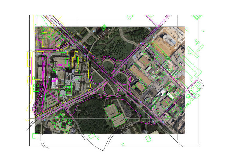
The ImageQuality command helps you control the display quality of images. The quality setting affects display effects; high-quality images take longer to display. Changing the setting updates the display immediately without regenerating the drawing.
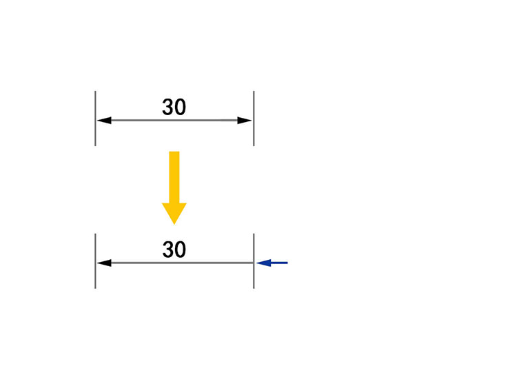
The expected command AIDIMFLIPARROW is now supported in ZWCAD 2018. Click a dimension node to flip the arrowheads in or out.
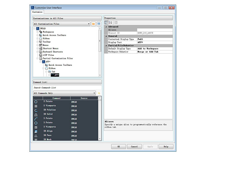
Customize the classic interface. Partial CUI is supported.
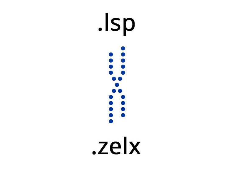
Lisp Compiler is used to compile .lsp file to .zelx formats, which can be loaded on ZWCAD. It helps users to run Lisp programs more efficiently and developers to protect source codes in security.
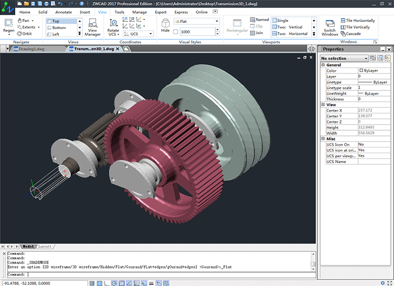
While using commands in Solid Menu, user can preview the 3D model in thedrawing area. The previews are dynamic to show their positions and sizes.
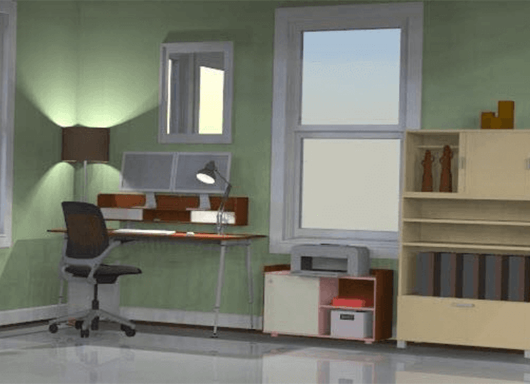
ZWCAD now can create a realistic rendering of a 3D model to help user to have a clearer vision of a conceptual design.
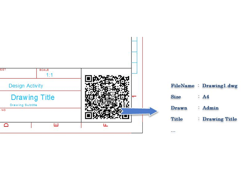
In design phase, to generate codes including information like project name, drawing name, designer, audit, data and etc., user can use rich scan tool to enter this information to drawing pool effectively just by scanning the codes.
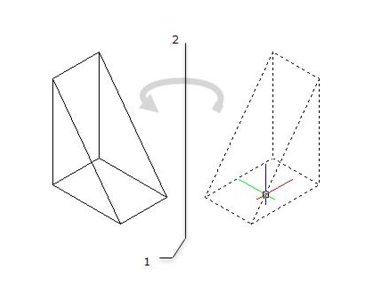
ZWCAD now supports command ROTATE3D to specify the axis of rotation usingeither two points.
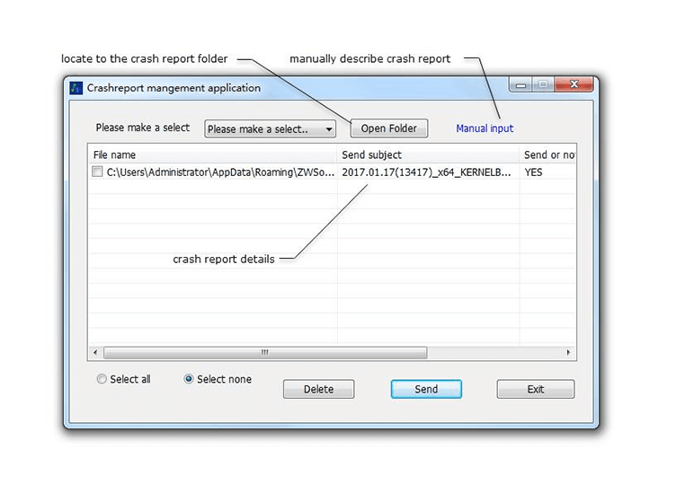
User can locate to the folder that stores these reports, check the error reports that has been sent or unsent, and send those unsent ones optionally so as to help assess the stability while working in user environment and improve the quality of ZWCAD.
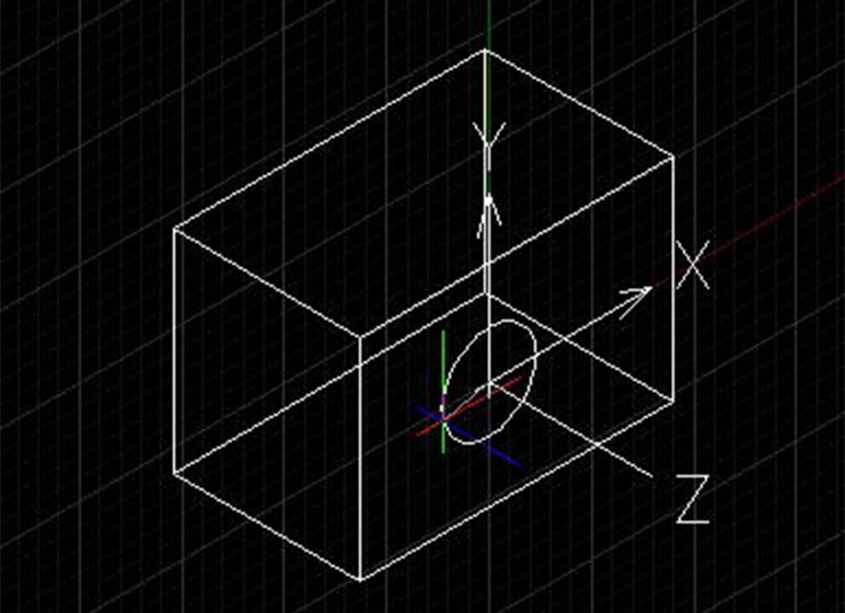
When user moves the cursor over a 3D solid planar face during the command, the program will align the XY plan of the UCS with the planar face automatically. After the command is finished, the UCS returns to previous setting.
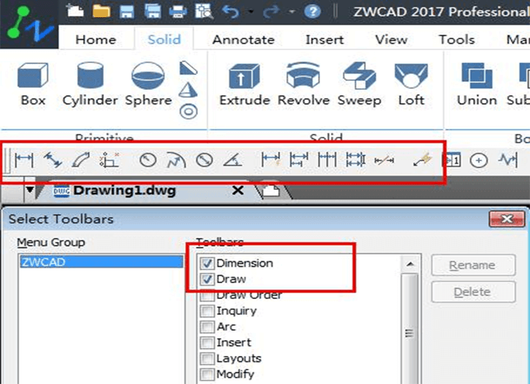
ZWCAD can callout tool bars in the ribbon interface.
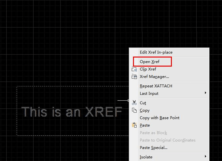
User can open selected external reference by right-click shortcut menu.
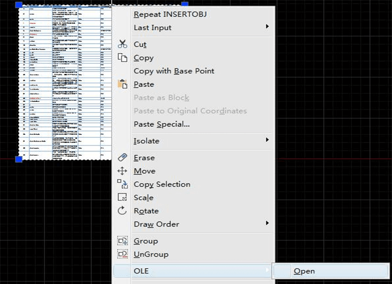
User can open selected OLE objects by right-click shortcut menu.
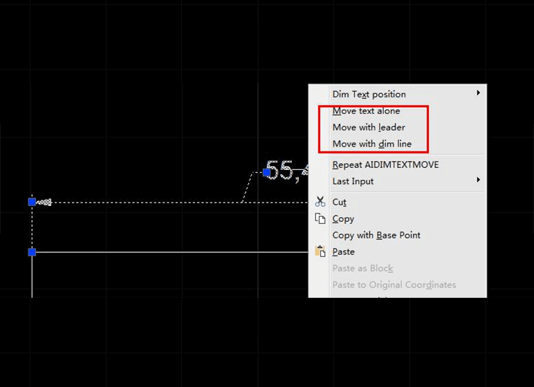
User can move dimension text by right-click shortcut menu.
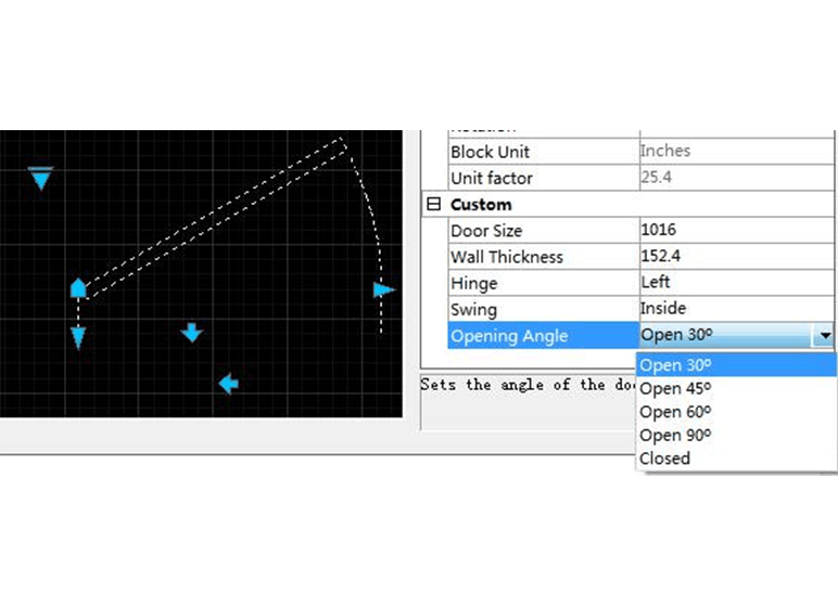
Besides manipulating the geometry of the dynamic block by custom grips, now ZWCAD 2017 SP1 also supports editing the custom parameters in Properties panel.
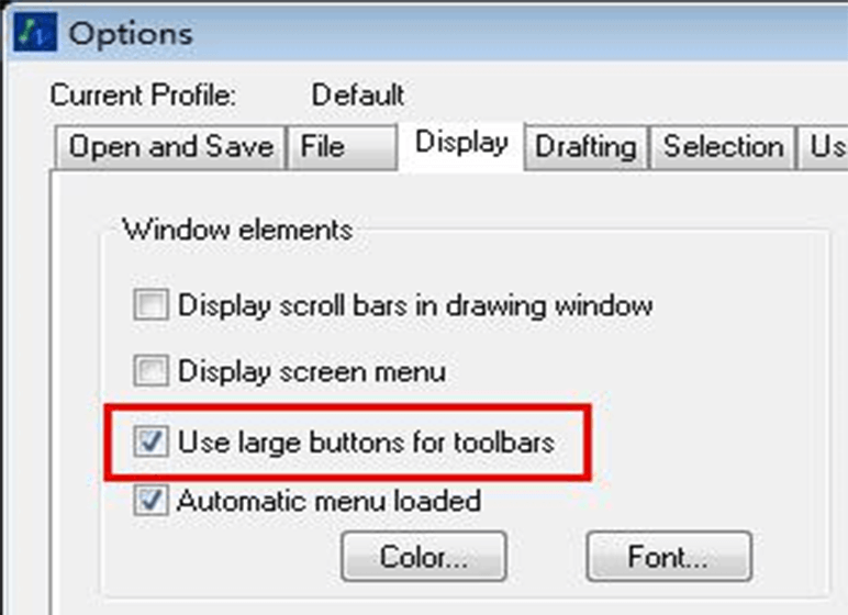
It supports displaying buttons in a larger format at 32 by 32 pixels, thus provides better compatibility for high-resolution screen.
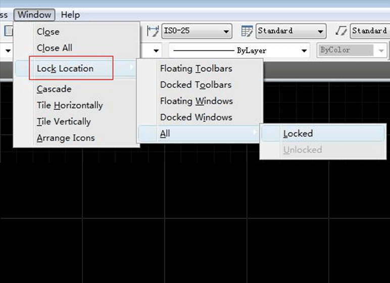
ZWCAD 2017 SP1 allows user to lock the location and size of toolbars, and docked windows such as Tool Palettes and Properties palette.
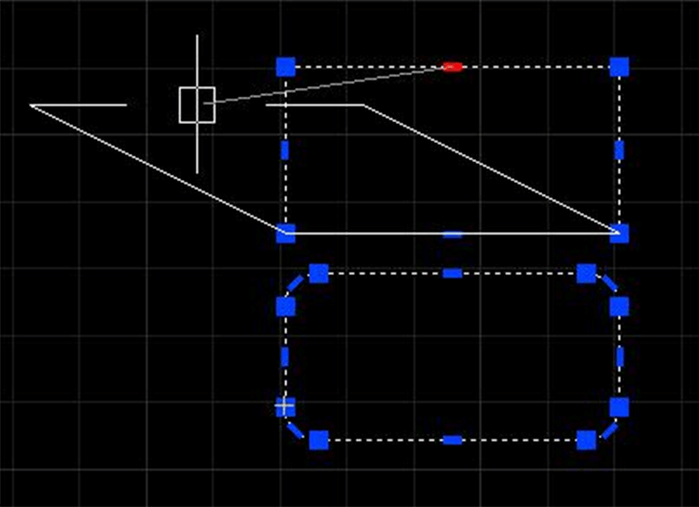
● Magnet: the cursor will automatically pick the nearby grip in editing mode, and the grip will display in different color
● Edit: Space/Shift key switches the edit mode stretch / scale / rotate / mirror / move
● Multiple grips editing
● Better pline grips editing
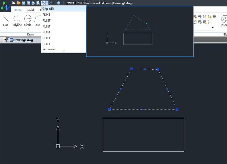
● Command: undo snapshot
● List preceding operations, you can choose the undo/redo point, and preview the result
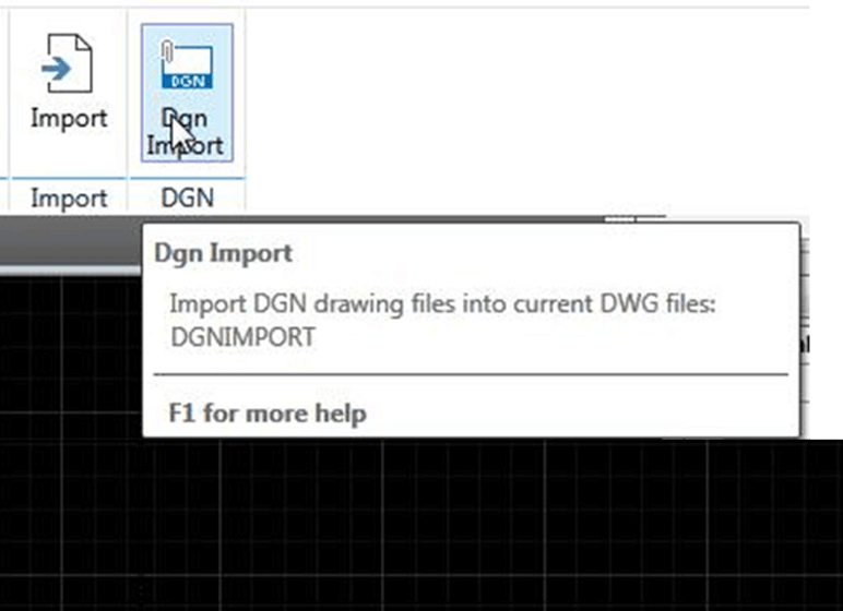
User can now import data from DGN file to DWG file with SGNIMPORT command. Supports MicroStation V7 and V8 DGN file format at the time being.
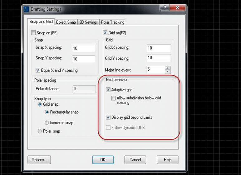
The grid can adaptively change grid line density when zoom in or zoom out.
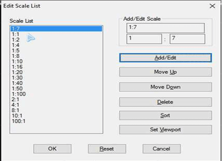
User can add/edit the scale value to the scale list, or change the position of selected scale value, and sorts the values in the list, which could be applied to the layout viewports.
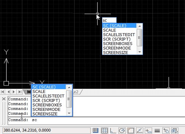
With dynamic input feature, user can get dynamic prompt when you input the commands or system variables in the command line or the drawing area.
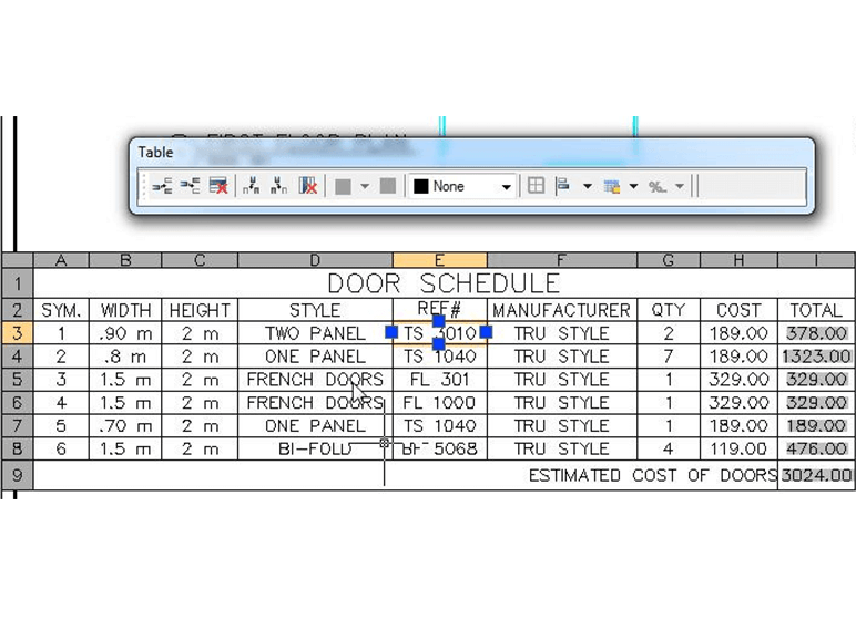
Double click the table, or call TABLEDIT command, user can in-place edit the table: insert row/column, delete cell, merge cells, unmerge cells, lock cells, align cells. User can see that we have column and row labels for the table now.